BattTest V1 has been succeeded by BattTest V2 using custom hardware which will be described in a future post.
Click here to go to this project on GitHub
Now that the Jaguar motor controller has reached its end of life, they are accumulating in FRC team shops. Team 548 had around two dozen hiding in a tote. One use I found for them is testing batteries. After many brownouts during the 2016 season, we wondered if the batteries were faulty. My first plan was to use a robot, but it was hard to eliminate variables, noisy, and overheated motors. After returning to the drawing board and doing some digging, I found a roll of steel high-temperature wire which had a total resistance of around 0.58Ω, able to burn about 14 amps at 8 volts for hours on end. With a spare Jaguar, box fan, and that wire, I constructed and programmed a 10A constant current load with PC data-logging.
Disclaimer
Due to license issues, the PIDController source is no longer included but was sourced from the LeJOS project with modifications. Seventeen Acres Battery Test V1 is licensed under the MIT license. USE THIS SOFTWARE AND GUIDE AT YOUR OWN RISK. This software is not designed for and does not have adequate safety mechanisms for use with actuators, precision applications, safety-critical applications, or industrial use. Use this software for testing in a non-production environment only. Do not use this software or setup described unsupervised. Even use with a resistive load, as described below, can cause damage, injury, fire, or death. This software is in a rough state and may malfunction.
Hardware
- Battery connector (I used clamp jumper leads)
- ≤40A circuit breaker or fuse (I used a 2009-14 PDP with 40A breaker)
- Black Jaguar motor controller
- Insulated steel wire
- Wire rack
- 6P6C RJ25 cable
- DB9 to RJ25 RS-232 adapter with CAN terminator
- RS-232 DB9 port (I used a TRENDnet TU-S9 USB to RS-232 adapter)
- Box fan
- Windows PC
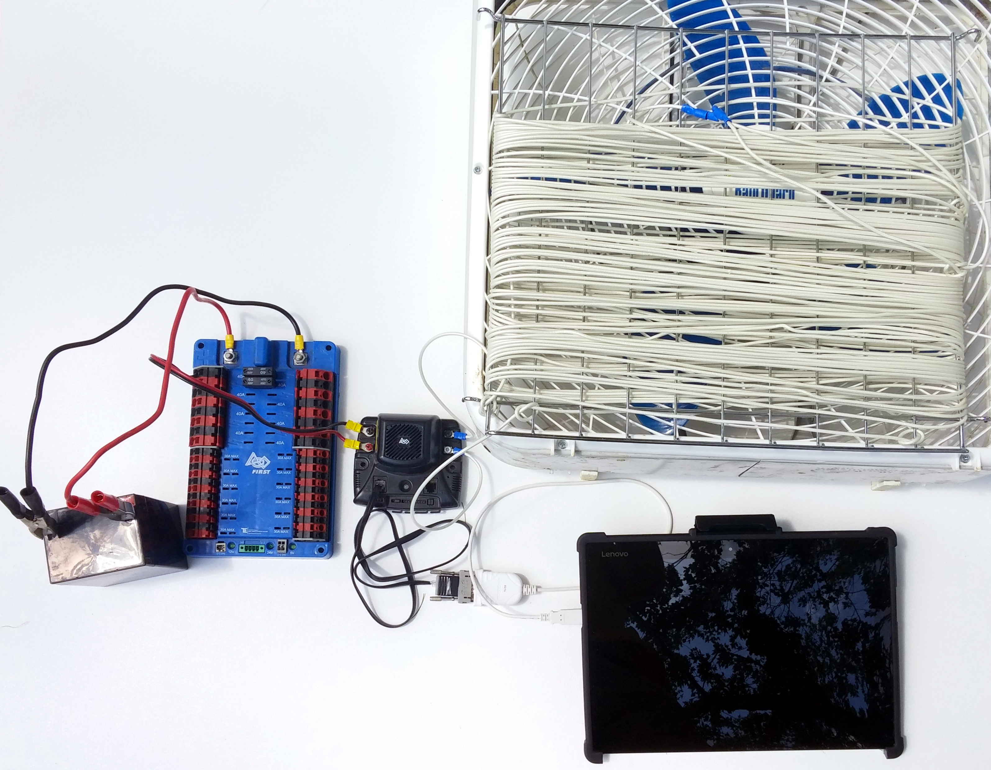
The input side of the Jaguar is wired similarly to a normal robot but the main breaker is omitted since there is only a single 40A limited load. The steel wire is split into three separate sections in case a different resistance was required. All three sections are connected in series across the Jaguar’s output. The load panel is then placed in front of a box fan. Since black Jaguars have an internal RS-232 to CAN bridge, it is connected via its 6P6C RJ25 port to a USB to RS-232 adapter with a DB9 to RJ25 converter attached to the PC. This setup is also used for firmware updates and ID management in normal FRC usage.
Software
The most straightforward way to control and monitor a Jaguar would be to use a cRIO, but FRC limitations make them tedious to use for static operations. A second option would be connecting to the Jaguars to a PC application using the serial libraries in Java. While the Jaguars have RS-232 serial, the protocol is not well-documented or simple. The BDC-COMM Windows software used to configure and test the Jaguars, however, has an often-ignored CLI mode which, although somewhat cryptic, has enough documentation to be useful. The CLI mode enables all of the important functions of the Jaguar including PID, sensors, and output control. The Battery Test java application launches the BDC-COMM CLI terminal internally and then sends commands to that to operate. In constant current mode, the Java application runs a PID loop on the input current (calculated with output voltage and current, input voltage, and experimentally determined efficiency of .94) to output a set voltage to the Jaguar via BDC-COMM. Every 10 ms, the status values, set-point, and the energy integrator are updated. Every 100ms, a snapshot of input voltage, current, power, and energy and output voltage, current, power, and energy is logged to a CSV.
Operation
Prerequisites
- PC running Windows (tested on Windows 10)
- Java 8 runtime
- Black Jaguar with non-FRC firmware v8161 and CAN ID 1
- BDC-COMM extracted and the Battery Test jar downloaded to the same directory
Use
- With the load connected to the output of the Jaguar, attach the leads to the battery, powering on the Jaguar.
- Connect the USB to serial adapter to the computer
- In Device Manager note the COM port connected to the Jaguar
- Prepare for the load output to energize
- Open the Battery Test jar and enter the appropriate COM port number. Note: On some Java installations, you will need to open a command prompt window in the location of Battery Test and run the following command:
java -jar "Battery Test.jar" - For Constant Input Current Operation:
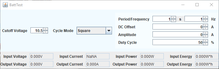
- Set the cutoff voltage to a reasonable value (default: 10.5V)
- Select ‘Constant’ cycle mode
- Set DC Offset to the desired input current. Note: this current must be less than what the load draws at the cutoff voltage. For example. with a 2Ω load and a 10V cutoff, the maximum possible current is roughly 5A. For smoother operation stay well below that threshold. Note that very low resistance loads can cause damage to the Jaguar since the software cannot respond quick enough to handle the massive current.
- Wait roughly one and a half to two hours for the cutoff voltage to be reached. A window will pop up with the energy used during the test. Closing the pop up will exit the application. Note: The output may not be fully disabled when the test ends. Disconnect the battery immediately after the completion of the test.
- For Cyclical Output Current Modulation:
- If testing batteries, set the cutoff voltage to a reasonable value (default: 10.5V)
- If not testing batteries, set the cutoff voltage to a sufficiently low value
- Program each of the fields available for the selected wave function to determine the output waveform.
- If testing batteries, continue with step 4 in the “for Constant Input Current Operation” section
Results
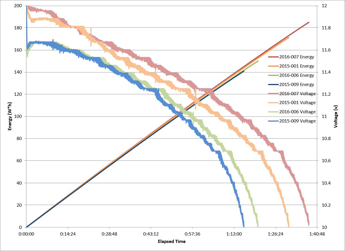
For the batteries I tested (an unused 2015 MK battery (2015-009), a KoP battery from 2015 (2015-001), and two used 2016 MK batteries (2016-007 and 2016-006)) no correlation could be found between brand or age and capacity. For better results, real battery connectors should be used, since a 30mΩ input resistance difference would cause the .3V voltage drop observed in 2015-009 and 2016-006.
Thanks to FRC team 548, the Robostangs for supporting this project. They had no involvement with this publication and any views or statements presented in this article are my own.